File Systems
Data produced by programs need to be stored somewhere for future reference and there must be some sort of organisation so that we can quickly retrieve the desired information. A file system is responsible for this task and it provides an abstraction over the storage devices where the data is physically stored.
I/O devices
These are the hardware pieces used to provide input or output: keyboards, mouse, monitor, disks, etc. The following picture shows how they communicate with the CPU and memory:
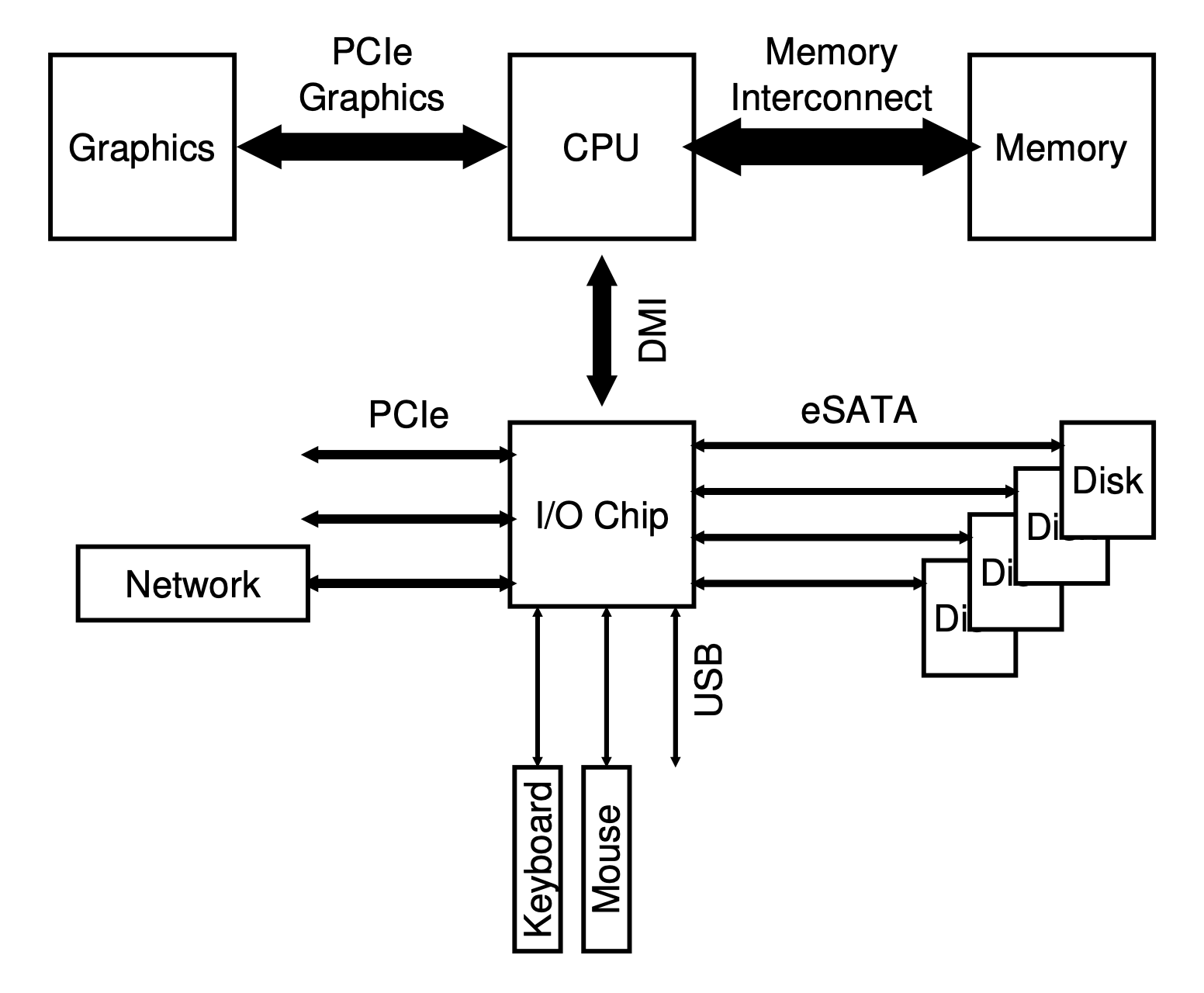
The communication between the CPU and these devices can be carried out in different forms.
Polling
The first form describe is polling where the OS waits until the device is ready to process commands. This is performed by polling the device register that indicates if it is busy or not. Then the data is written to the appropriate register and the write command is written to the command register.
The device detects it has work to do and the operation is performed. The host will then continue polling the device controller to see when the operation has finished. The relevant data or an error can be returned upon completion.

When the CPU takes the role of the host this model is called programmed I/O.
This simple model has a clear problem of being inefficient. The host wastes time polling the device while operations are being carried out and that time could have been used for some other task.
Interrupts
To mitigate that problem, another model was invented were the host issues the commands in a similar fashion but instead of polling the device to detect the end of an operation the host switches to another task and whenever the device finishes its job it will then raise a hardware interrupt to indicate as such. Between each instruction the interrupt-request line is checked and if one is present the corresponding interrupt-handler is executed.
The benefit of interrupts is that it allows for tasks to overlap. When a task issues an I/O operation the host can issue the request, switch to a different task and when receiving an interrupt it switches bask to the previously asleep task to continue its execution.

A problem that this approach has is when the I/O is too fast and the cost of switching tasks takes longer than the I/O operation itself. In this case if the host kept polling the controller it would’ve been faster. Sometimes it is a good idea to use a hybrid approach that polls for a little while and if the device is not done then switch to the interrupt model.
Another issue that might arise with interrupts is when you have a network device that is receiving a huge amount of data and keeps interrupting the host all the time. This causes a livelock where the host is only processing interrupts and not progressing user-level tasks. In this case, it is better to occasionally poll the device.
And finally, another optimisation with interrupts is to have devices waiting for a bit before issuing the interrupt. Other tasks might complete in this time, more interrupts can be coalesced in a single interrupt and the overhead of processing multiple interrupts is lowered. This approach of course requires a balance between waiting too long which would increase the latency of a request.
Direct Memory Access
Both approaches described before suffer from a common problem: when a large chunk of data needs to be transferred the host spends quite some time copying the data to the device data register and not working on a different user-level task.

The solution to this problem is called direct memory access (DMA). A DMA controller is responsible for orchestrating the data transfer between devices and the main memory. It allows more efficient data movement by relieving the host of that job.
The way it works is the following: the host issues a command to the DMA controller by telling it where the data lives, the amount that needs to be transferred, and where it needs to go to.

Device interaction
The host communicates with the device controller either via I/O instructions or memory mapped I/O. The method using instructions is what you expect by the name: the caller specifies a register with the data in it and port to identify the device. Executing the instruction leads to the desired behaviour.
In memory mapped I/O the device registers are mapped to the memory and the host can issue read/write commands as if it was dealing with main memory. Those commands are then routed to the device.
Hard Disk Drives
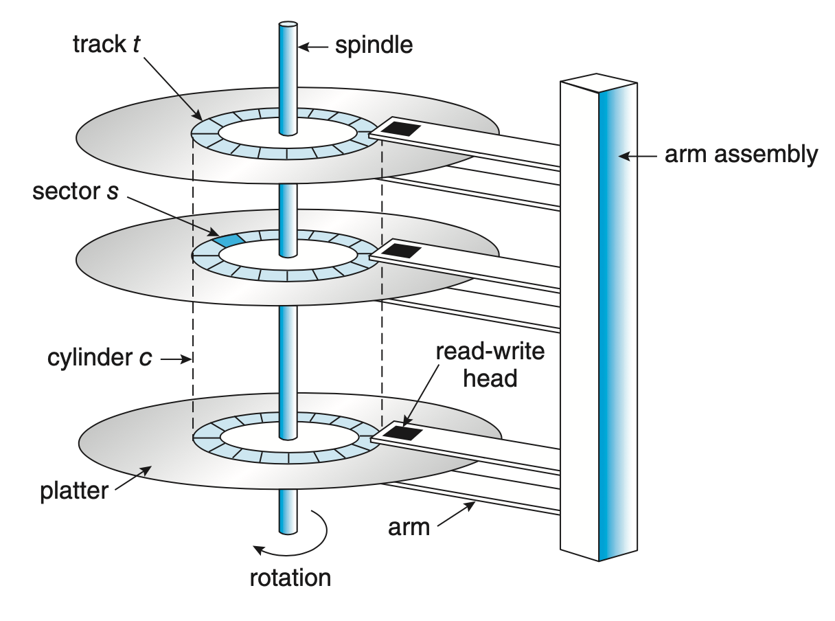
HDDs consist of several platters, a circular hard surface covered with a magnetic material. Writing to the disk is done by magnetic induction and information is read by detecting the magnetic pattern on the platters. Both surfaces of the platters are writable.
The spindle hold them together and it is connected to a motor that spins the platters while the power is on. The rotations per minute (RPM) measures the rate of rotation of the platters. The values are usually between 7,200 to 15,000 RPM.
The surface of a platter is divided logically into circular tracks. Each track is subdivided into sectors. These have a fixed size and it is the smallest unit of transfer. The usual sector size used to by 512 bytes but new disks have the sectors sized at 4 KiB.
The disk head which is connected to the disk arm is the piece doing the writes and reads. There is one head per surface. The arm is responsible for moving all the heads positions over the desired track.
I/O model
The way a request is serviced by the HDD depends on which sector it should operate. If the head is already over the track containing the sector it needs to wait the rotation to position the sector under the head. The time waiting is called rotational delay.
If the head is not on top of the track containing the sector then it has to be moved over the correct track. This process is called a seek.
When the sector passes under the head the data transfer is performed; either writing to the disk or reading from it.
Writes to the disk do not always mean the information has been written in the surface. Disks have caches that are used to cache read information; for example, when over a track it might cache several sectors to serve subsequent reads faster; or to write information in a similar fashion. Write back is the name given when the disk caches the information but reports the write has been performed and write through is when the disk reports the write is completed after it is on the platter surface.
Access patterns
Information can be access randomly or sequentially. HDDs perform better when with sequential I/O since it doesn’t need to seek or wait for a rotation.
That is the reason why you see a lot of systems describing methods or using structures that favour sequential I/O in order to maximise their performance.
Disk scheduling
Another way of improving the efficiency of a HDD is to decide which requests to serve first. There are different algorithms for disk scheduling. In older systems this task was done by the operating system but modern disks have their own scheduler.
SSTF: Shortest Seek Time First
In this approach the request which requires the least amount of seek is the one serviced first.
A problem that can occur with this approach is called starvation. Imagine a stream of requests coming in and they are all close to the inner track where the head is at the moment. Any requests for the outer tracks is ignored and thus you have the starvation situation.

FCFS: First-come, first-served
This is a classic approach used in queues where the requests that arrived before are serviced before requests issued at a later point in time. The problem with this approach is that performance can be severely degraded if the disk arm has to move up and down all the time because the requests are being issued to different tracks that are far apart. Compare this to the SSTF where the requests in nearer tracks would’ve been serviced before so the performance for those would’ve been improved in comparison to FCFS.

SCAN
The SCAN algorithm moves the head in one direction until it reaches the boundary of the platter and then moves back in the opposite direction serving requests along the way.
The following image shows a variant of SCAN called LOOK which instead of going all the way to the boundary of the platter and then switching the head direction it switches the head direction after the last request closest to the boundary is served.

C-SCAN
The circular scan (C-SCAN) algorithm does not serve requests in the opposite direction. When it reaches one end of the disk it moves back to the other and only then starts serving them. This idea is to have a more uniform wait time because with the SCAN algorithm requests for the inner tracks wait less time since they can be served when the arm is moving from one end to the other. With the C-SCAN algorithm this doesn’t happen so requests in the outer tracks will have a wait time more or less similar to the inner ones.
The following image shows a variant of C-SCAN called C-LOOK which follows the same principle of the LOOK algorithm using the circular approach described above.

SPTF: Shortest Positioning Time First
The scan variations suffer because they do not account for the disk rotation. The problem arises if a request is issued to a sector in the next track from where the head currently is but the sector is almost a full-rotation away from the disk head.
In this case, a better choice would be to serve a request that is for a different track where the sector is closer to the disk head. This is the base of the SPTF algorithm.
Note that this decision depends on the seek time and rotational delay so that if the disk needs to seek to an outer track it has to be quicker than jumping to the nearest track and waiting for the rotation.
Other considerations
Sometimes it is useful for the scheduler to do I/O merging which consists of merging requests to subsequent sectors into one. This does not only mean that the requests will be served together but also means less overhead to the disk as it is one less request to serve.
Another problem that schedulers need to tackle is to when issue the I/O operation. Should it be done immediately upon receiving it from a program or should the system wait a bit?
When operations are issued immediately the approach is called work-conserving because it means the disks will never be idle if there are requests to serve. The other approach, non-work-conserving, can improve overall performance if “better” requests arrive during that waiting period.
RAID
A Redundant Array of Inexpensive Disks looks from the outside just as a normal disk where writes or reads are performed on its blocks. Internally, they are very different consisting of several disks, memory (volatile and non-volatile), and even with a processor inside.
The benefits brought by RAID are performance as multiple disks can be used in parallel. The capacity is also increased. And lastly, reliability can be improved because depending on the RAID level it can tolerate a loss of a disk.
These advantages are provided transparently as the OS does not need to change its interaction with disks. For the OS a RAID system looks exactly like if it were a single disk.
RAID-0
This level does not bring any redundancy to the system but improves the performance by striping the data across the disks. In other words, the data blocks are written to the disks in a round-robin fashion.
| Disk 0 | Disk 1 | Disk 2 | Disk 3 |
|---|---|---|---|
| 0 | 1 | 2 | 3 |
| 4 | 5 | 6 | 7 |
| 8 | 9 | 10 | 11 |
The capacity in RAID-0 is maximal as all disks are fully used. The performance is improved as all disks can be used in parallel as well. But with the cost that this level does not offer any reliability.
RAID-1
In this level the idea is to mirror the data across the array. So in a 4-disk array as above, the data would be mirrored in pairs.
| Disk 0 | Disk 1 | Disk 2 | Disk 3 |
|---|---|---|---|
| 0 | 0 | 1 | 1 |
| 2 | 2 | 3 | 3 |
| 4 | 4 | 5 | 5 |
The capacity is reduced as some disks are storing copies of data. Performance varies depending on the workload. A write to block 2 can occur while another operation happens on disks 2 and 3. Reads can be performed at either disk that contains a copy of the data. This level offers reliability as it can tolerate a loss of a single disk; two if you are very lucky having different copy disks being lost, 1 and 2 for example.
RAID-4
In RAID-4 instead of having disks being an exact copy of another it has a single disk storing the parity from the information stored in all disks. One way of calculating the parity is by using the XOR operation.
| Disk 0 | Disk 1 | Disk 2 | Disk 3 | Disk 4 |
|---|---|---|---|---|
| 0 | 1 | 2 | 3 | P0 |
| 4 | 5 | 6 | 7 | P1 |
| 8 | 9 | 10 | 11 | P2 |
Capacity is increased again in this level at the expense of having a single disk being used just for the parity. The reliability is the same as in RAID-1, the information in a lost disk can be reconstructed by using the parity data. The problem lies with writes where each write incurs also a write to the parity block and so they need to be serialised into that single parity disk. This is called the small-write problem.
RAID-5
To fix the small-write problem the RAID-5 level has what is called rotated parity. In this case, the parity is not stored in a single disk but each stripe parity is stored in different disks.
| Disk 0 | Disk 1 | Disk 2 | Disk 3 | Disk 4 |
|---|---|---|---|---|
| 0 | 1 | 2 | 3 | P0 |
| 5 | 6 | 7 | P1 | 4 |
| 10 | 11 | P2 | 8 | 9 |
| 15 | P3 | 12 | 13 | 14 |
| P4 | 16 | 17 | 18 | 19 |
This removes the bottleneck seen in RAID-4 as writes now can be parallelised as the parity lives in different disks.
Problems with RAID
Although RAID offers measures to overcome hardware issues it is not bulletproof. Pointers to a file could be wrong, incomplete writes can occur, processes could write to a file system data-structure and corrupt it. And not only software bugs can happen, the RAID controller could be faulty too.
One way of detecting these issues is by using checksums. The pointer to the data could have a checksum, then when the data is retrieved the checksum is compared and checked if there has been any issues. For example, in a RAID-1 setup if one copy has corrupt data; detected by comparing the checksums; and another copy doesn’t, the system can fix it by overwriting the corrupt data with the good one.
File System Interface
In virtualisation of storage two main abstractions have developed over the years: files and directories. A file is simply a linear array of bytes which you can read or write to it. The file system refers to a file by its low-level name: inode (or inode number). A directory has an inode like a file but instead of containing an array of bytes it contains the list of files present in that directory. This list is usually a tuple of the following form: (user-readable name, low-level name).
Creating files
Files are created by calling the open() syscall:
int open(const char *path, int oflag, ...);A successful call returns a file descriptor which is an integer private to each process. Other operations expect the file descriptor as argument to indicate which file they should act on.
Reading from files
To read from a file the read() syscall is used:
ssize_t read(int fildes, void *buf, size_t nbyte);Along with the file descriptor it also expects the amount of bytes to be read into the given buffer.
Writing to files
To write to a file similar syscall is used: write():
ssize_t write(int fildes, const void *buf, size_t nbyte);The arguments are the same as in the read() syscall but in this case the buffer is used as the input and the amount of bytes specified is the maximum of bytes that should be written.
Random reads and writes
The operations were described following a sequential access pattern. To perform random reads and writes the lseek() syscall is used.
off_t lseek(int fildes, off_t offset, int whence);When lseek() is called, the file offset is positioned to the given offset and any subsequent read or write is performed from that location instead. The whence argument controls how the seek should be executed.
If whence is SEEK_SET, the offset is set to offset bytes.

If whence is SEEK_CUR, the offset is set to its current location plus offset bytes.

If whence is SEEK_END, the offset is set to the size of the file plus offset bytes.

If whence is SEEK_HOLE, the offset is set to the start of the next hole greater than or equal to the supplied offset.

If whence is SEEK_DATA, the offset is set to the start of the next non-hole file   The definition of a hole is provided beloweregion greater than or equal to the supplied offset.
Note that calling lseek() does not perform a disk seek. It just adjusts the position within the structure used by the file system to indicate where the next operations should be executed from.
Open file tables
Flushing writes to persistent storage
When a process calls write() it does not necessarily means the data will be immediately written to persistent storage. Writes are buffered to improve performance and because of it if an application requires the data to be immediately written to disk it needs to call fsync():
int fsync(int fildes);This forces a flush of all dirty data to disk along with any modified attributes. Note that the disk itself might have a buffer as well and the data could be physically written to disk at a later stage.
Sometimes it is also necessary to call fsync() on the directory itself to reflect the changes; for example, when creating a new file.
Renaming files
To rename a file the rename() syscall is used:
int rename(const char *old, const char *new);An interesting aspect of this syscall is that it is implemented as an atomic operation.
Removing files
Removing files uses a syscall that is not so obvious by its name:
int unlink(const char *path);The unlink() function removes the link named by the given path and when the reference count of links to a given inode reaches zero, the associated resources with the file are reclaimed and thus the file is removed.
Hard links
By understanding how hard links work you will understand why unlink() is used to remove files. One can use the link() syscall to make hard links:
int link(const char *path1, const char *path2);When this operation takes place, path2 and path1 will share the same inode. This inode will have a reference count of 2 to correctly identify that two user-readable paths are associated with it. And that is why a unlink() syscall exists and is the one used to remove files.
Symbolic links
Another type of links that can be created are symbolic links.
int symlink(const char *path1, const char *path2);This type in contrast with hard links creates a new type of file. It does not share the resources like a hard link does. So when the file being pointed at is deleted the symlink will have a dangling reference. In the hard link case, because the inode is shared, unlinking one file does not leave the other with a dangling reference.
Permission bits and Access Control Lists
To control which users have access to certain files and directories there are two main approaches: using permission bits or acccess control lists (ACL).
The permission bit cases is the most common in traditional file systems where there are 3 groupings: the owner of the file, what group members can do with the file, and lastly what other users can do. The bits hold the permission for rwx: read, write, and execute a file. So when the permission bits has a value of 600 it means only the owner can read and write to the file. No one else will have access to it.
An ACL holds a list of who can and cannot perform operations on the file and directories. By being a more granular solution it allows for more customised controls than just setting permission for 3 fixed groups.
Mounting a File System
File systems are made accessible by mounting them. This is accomplished by executing the mount() syscall:
int mount(const char *type, const char *dir, int flags, void *data);Upon return the filesystem pointed by data will be available at the the directory dir.
File System Implementation
In a file system implementation the disk is divided into fixed sized blocks; usually 4 KiB. A large portion of those blocks are assigned to store user data. This region is called the data region. Another region of blocks is assigned to hold the inodes where the metadata about the files will live. Information such as which data blocks hold data for that file, permissions, etc live in the inode. Then, to track which data blocks and which inodes are free, the file system allocates blocks for that reason. The implementation could be as a free list where each free pointer points to the next or as a bitmap where each index set to 1 indicates a free slot and any set to 0 indicates it is occupied. Finally, there is the super block containing information about the file system itself: how many inodes and data blocks exist, where the corresponding blocks start, and so on. The figure below gives an idea on how all of this is laid out in a simplified file system:

Inode
The inode is one of the most important structures of a file system. It holds metadata about the file such as permissions, size, and the location of the of the data blocks that make the file itself. The inode table in a more detailed view looks like following:

To fetch the data corresponding to an inode, the system has to calculate the offset where the data is located in the inode table. Basically something like the following:
blk    = inodeNumber * size_of(inode_t) / blockSize;
sector = (blk * blockSize + inodeStartAddr) / sectorSize;
The structure of an inode is similar to the following structure:
Pointing to data
The inode needs to have a way of pointing to the actual data blocks that assemble the file. The simplest way is to have direct pointers. In this case, each pointer points to a block that has some of the file data. The problem is that large files; where the size exceeds the number of direct pointers an inode can have; are not supported in this mode.
The inode needs to have a way of pointing to the data blocks that assemble the file. The simplest way is to have direct pointers. In this case, each pointer points to a block that has some of the file data. The problem is that large files; where the size exceeds the number of direct pointers an inode can have; are not supported in this mode. One way of overcoming this issue is to use indirect pointers, which instead of storing user data they store pointers to blocks that hold user data. For larger files, another layer of indirection is added with double indirect pointers. And for even larger files, triple indirect pointers are put to use.

To give an idea of the largest file size that each level permit let’s run an example considering that each block size is 4 KiB. Research has shown that the majority of files are small [3] so 12 direct pointers would allow for files up to 48 KiB. Considering that each pointer takes 4 bytes, a single indirect pointer would then allow a file to be up to around 4 MiB:
(12 + 1024) * 4 KiB
With the addition of double indirect pointers the size would jump to around 4 GiB:
(12 + 1024 + 10242) * 4 KiB
And finally, with triple indirect pointers the files could have a size of around 4 TiB:
(12 + 1024 + 10242 + 10243) * 4 KiB
This approach might no be very efficient for handling large files. For example, a file of 100 MiB requires 25600 blocks to be allocated. This can give you a sense of how much impact on performance could happen in case the blocks were fragmented over the disk.
To help with this situation some file systems use extents. In this approach, there is a single pointer and a length to tell that the data starts at the address of the pointer and runs for the given length of blocks. In our example above, the file would be described using a single extent of size 100 MiB. Multiple extents can be used to support larger files.
Directories
Directories can be represented using a list to register all the files contained in that directory.
struct Dir {
    // metadata ...
    entries: Vec<DirEntry>,
}

struct DirEntry {
    inumber: usize,
    name: String, // TODO: check if fixed or not
}
This approach can be slow if a directory has a large number of entries because each time it needs to find a given entry it has to perform a linear search on the list of entries.
This can be mitigated by maintaining the list sorted and thus using binary search at the expense of moving data around when creating and deleting files to maintain the list sorted.
Another approach is to use hash tables [4] in order to have O(1) lookup. And also one could use a balanced tree for the same purpose.
Allocation
The file system needs a way of knowing which blocks and inodes are free. One of the most basic ways of managing this is by using free lists. The idea is to have a pointer in the super block pointing to the head of the free list and each element in the list pointing to the next free block. When a previously used block is freed it can be returned to the tree and then reused.

A problem with free lists is that sometimes multiple entries would be required if the available space in the current free entry is not enough. This can lead to a fragmented disk and thus performance decreases with multiple disk seeks.
Another idea is to use bitmaps. Each position has a bit indicating whether the block (or inode in case of inode bitmaps) is free.
011100000111In the example above, blocks 1, 2, 3, 9, 10, and 11 are free while the others are occupied. One aspect that requires consideration is the amount of space required for bitmaps. Assuming a disk of 500 GiB with blocks of 4 KiB means around 16 MiB just for the storing the bitmap.
One trick that is usually employed by file systems is to preallocate blocks when files are created. In case the file uses these preallocated blocks it will benefit from having a contiguous set of blocks removing the necessity of a disk seek for example. Of course, if the file doesn’t require the preallocated blocks the file system returns them to the pool of free blocks.
Access paths
Read
When reading from a file the file system needs to traverse the entire path, visiting each inode along the way until reaching the inode for the desired file. Assuming the user has permission to access the file the file system consults which blocks are associated with the file and can read the desired data from them.
Write
To write to a file the same process has to happen to find the corresponding inode. If a new block is required for the write the file system has to allocate the block, update the associated information (bitmap and inode), and write to the block. So one write operation requires five I/O operations: one read to the bitmap, one write to mark the new block as occupied, two to read and write to the inode, and one writing the data in the block. This number can increase when creating a new file because now the associated information of the directory has to also be read and written to reflect this new file, and operations to create a new inode.
Caching and buffering
Usually, operating systems use a unified page cache to cache memory pages and file system pages in the same region1. This allows for more flexibility when partitioning the memory depending on which component needs more memory at a given time: processes or file system.
Another technique employed is write buffering. In this case, the write are not immediately issued to disk. Instead, these writes are buffering for anything between five to thirty seconds. This opens up the possibility of batching the writes and reducing the number of I/Os when the same blocks are updated by subsequent operations; bitmap region for example. In case a certain write is later discarded; by deleting the file; the operation is avoided altogether.
A possible problem is that in the event of loss of power or a system crash, all the data currently buffered in memory is lost. To avoid falling in this case some programs use fsync() to force the writes to disk.
Locality
The ideas presented so far can over time lead to a fragmented disk and impact performance. Consider the following example where files A, B, C, and D have data stored as follows:

If B and D are deleted, the disk layout becomes the following:

Then if a new file E composed of four blocks is added the disk layout will look like the following:

As you can see, now file E is dispersed in the disk and if a sequential operation is required it will possibly result in a disk seek. There are tools that can help with this issue by defragmenting the disk and grouping the blocks again.
One solution to this problem is to group blocks into a block group. ext4 uses 128 MiB block groups, for example [5]. Each block group thus have the following structure:

Note that the super block is replicated across the block groups. This ensures that if one gets corrupted a different copy can be used to mount the file system. The inode and data bitmaps correspond to the group’s inodes and data blocks, respectively. The inode and data block regions are similar to before.
The idea of building these larger groups is that when deciding where to place the files the file system can apply some heuristics in order to reduce fragmentation and maintain a good performance over time.
One obvious idea is to place related files together in the same group. So for example, files under the same directory are kept in the same block group. Data blocks of files are also placed in the same group as their inodes so that the seeks are not too far.
Different directories are placed in different groups so that when creating new files the impact will be minimal across directories.
Large files require a different approach. Imagine if the file system placed all data blocks of a large file in the same group as its inode. Later, there wouldn’t be enough space for other small files in that same group. So what is done instead is to place the direct pointers in the same group (usually 48 KiB), and then put the next large chunk in another block group (with low utilization). And this process is repeated so each next large chunk is placed in a different block group.
The same idea of spreading the data blocks can be used with popular directories. The root directory is an example of this. Rather than placing all child directories in the same group and possibly running out of data blocks for the child’s own files, these are instead spread out through the disk.
Crash Consistency
fsck
The file system needs to have mechanisms for checking its consistency and recovering after a system crash or power loss, for example. One well known technique is to use a fsck (file system checker) that inspects the metadata in the file system and compares to the stored state on disk while trying to fix any incosistencies it finds. Not all issues can be fixed by fsck though, resulting in total loss of files and/or directories and sometimes even requiring human intervention. Another downside of this approach is that it is slow. It requires a full scan of the disk and as disks grew in size the process became even slower.
Journaling
Another popular technique is journaling (or write-ahead logging). The idea is that before updating the structures in place, a little note describing what is about to happen it’s written to the journal region. If a crash happens, this journal can be replayed and have the structures in a good state. So, now as you can imagine, the structure on disk must have a new section to record these notes:

When a write operation happens, the journal needs to be updated accordingly. The update is done by writing transactions to the journal. The format requires an initial part containing metadata about the transaction itself: addresses of the blocks and inodes involved in it, and a transaction identifier. Then the contents of the involved blocks are written, and finally, once the data is safely on disk, a piece of data is written to mark the transaction as committed.

Once the transaction is committed the contents of the update are written to their final on-disk locations. This is called checkpointing.
Note that there are three steps in this process:
- Transaction begin: write transaction metadata and contents to the log.
- Transaction commit: after the previous step has completed and is safely on disk the transaction commit block is written.
- Checkpoint: write the contents of the transaction to their final destination.
The reason for splitting the transaction write into two steps is that the disk could reorder the writes for the transaction block and in the end an entry in the journal could be left without the data to be written:

In case a crash happens before the data is written to the transaction and the log replay is performed there will be no way of knowing if the garbage inside the region where the data should be is real or garbage because that section is user defined data so it could be anything.
One way of removing this extra middle step and thus save one disk rotation (after writing the initial parts of the transaction) is to write checksums of the contents in both begin and end blocks of the transaction and write the entire transaction in a single step. Then when replaying the file system can compare the checksums and detect any inconsistencies.
One way of improving the performance when using a journal is to batch log updates. The file system waits for a short period of time and puts all operations that happened in that period in single transaction. An example of a case where this is beneficial is if two files are created in the same directory one after the other. Without batching, there would be two transactions updating to the directory metadata which would mean two writes to the same block containing the directory information. But by batching these updates only a single write to the block is required.
Another aspect of journaling is that the journal cannot grow without bounds and take too much space that would have been used for user data. The journal has a fixed size and it is reused and it is sometimes referred as a circular log. To achieve this journals have a super block as well to record information such as where the current log of transactions start and end. When the checkpoint step is performed for a transaction the journal super block is updated accordingly and the space used for a transaction that has been checkpointed can be used in a subsequent transaction.

If you notice, the journaling system described so far doubles the writes for data blocks. One write to the transaction and one to the on-disk location. Some file systems such as ext4 will by default not write twice. They only write the data blocks to the on-disk location and the transaction only contains metadata. This type of journaling is called ordered journaling.

In this case, the data is written to disk before the transaction is logged. But this mode opens the possibility of losing data since a crash can occur after writing to the disk but before logging it in the journal.
A final note on journaling relates to the process of deleting files when using ordered journaling. For example, imagine a file is created and the data block corresponding to the directory that includes the file is updated as well because directory information is considered metadata so it goes in the journal. This is a different approach than data blocks for files that in ordered journaling are not written to the log. The journal might look like the following:

Then, assume the directory is deleted. Subsequently after, another file is created in a different place but ends up reusing the block that belonged to the now deleted directory: block 23.

If a crash happens before the file system can mark the first transaction as completed the log replay would overwrite the data block 23 and thus the contents of the second file are overwritten and lost; they are not part of the second transaction.
To solve this problem the file system could write a tombstone transaction in the log when something gets deleted. Before log replay it would scan these tombstones and ignore any relevant transactions based on that.
Other approaches
Journaling and fsck are not the only approaches for keeping the metadata in a file system consistent. Another technique called copy-on-write (COW) never overwrites files or directories in place. It places new updates in different and unused locations on disk and when these are safely stored it switch the root struture of the file system to use the new root with the updated information.
Another approach is called back-pointer based consistency. In this case every block has a pointer back to the owning structure; an inode for example. In the event of a crash the file system can then inspect the forward pointers and back pointers to detect any inconsistencies.
Log-structured File Systems
The Log-structured File System (LFS) takes an innovative approach by buffering all writes; including metadata; in an in-memory structure called the segment and once a segment is full it gets written to an unused part of the disk in a single operation. The idea here is to maximize the performance by reducing the amount of writes and not only that but also by performing a long and sequential write instead of several random operations.
As an example, imagine two different files had some data written to them. After buffering enough; a typical segment size would be a few MiB; LFS would write the new data blocks of one file, then its inode. After that the new data block for the other file would be written followed by its inode:

One thing that comes to mind is how complicated it is to find the inodes since they are spread across the disk. And not only that but when a new update is issued the inode moves to a different place.
For this reason, LFS has an inode map (imap) which keeps track of the most recent version of an inode. Given an inode, the imap will return the location of the latest version. The imap is written to disk along the rest of the segment:

As you might have noticed, the solution solves only half of the problem. The imap also keeps moving. The next piece introduced in LFS is a fixed location called the checkpoint region (CR) which stores pointers to the latest pieces of the imap. Thus, by reading the checkpoint region the file system can rebuild the imap.

To read from a file, the checkpoint region is the first structure consulted. From there a read to the imap blocks can be issued and cache the entire imap in memory for subsequent reads. From the imap the file system can obtain the exact location of the inode referring to the file and finally read the data blocks pertaining to it.
Directories work in a similar fashion as files on LFS. They are also stored in the new disk region, and the imap portion is updated to include the information about the new location of the directory as well.

When a file is read, the imap is used to find the inode of the directory, then based on the location of the directory blocks pointed by the inode the file system would find the mapping from user-readable name to inode of the file and go back to the imap to find the location of that inode which would finally be checked to find the exact location of the data blocks of the file.
As the file system keeps writing updated information in different locations of the disk the old versions of files become garbage and could be deleted so that space can be reclaimed and reused. Or these old versions could be kept around for a while and allow users to restore older versions.

The way LFS does garbage collection is by periodically checking partially-used segments, determining which blocks are still in use, then writing new segments with just the live blocks. Once that is done, the old segment space can be reclaimed.
To determine which blocks are alive in a segment, a segment summary is placed at the beginning of a segment. This summary includes the inode number for each data block within that segment and its offset. A block is considered alive if the most recent version of an inode; obtained by looking up on the imap; points a given file offset to the same block that the information stored in the segment summary points to.

One way of reducing the number of reads is to include a version number on the summary and whenever a file is deleted or truncated the version number is bumped so if the version in the imap is mismatched with the one in the segment summary there is no need to read the inode.
The approach used by LFS for crash recovery is as follows. Two checkpoint regions exist in the disk, one at each end. These regions are alternately updated and when doing so it splits the operation in three parts: write a header with a timestamp, then the body of the checkpoint region; with updated pointers; and finally, another header with the same timestamp. In case of a crash, the system can compare the timestamps and detect an inconsistency. And after a crash, the checkpoint region with the most recent and consistent timestamps is used so the recovery is based on consistent information.
Another step of the recovery process relates to the fact that the CR is not updated with every segment write. Updates to the checkpoint region occur every 30 seconds or so. If the system crashes between writing a segment to disk and updating the CR the segment information could be lost. To avoid losing valid data LFS uses a technique called roll forward. The last known checkpoint region is picked and from there it can read the last segment region that was successfully reflected in the CR. Each segment region has a pointer to the next so the file system can move forward reading new segments, check their consistency, and update the file system structures accordingly to ensure the files are recovered.
Solid-State Drives
Solid-state drives (SSDs) do not have moving parts like hard drives as they are built out of transistors like memory and processors. Unlike memory though, SSDs retain their information after a power loss which makes them an ideal candidate for storing persistent data.
The technology behind it is called flash memory where the most used type is based on NAND gates. An interesting aspect of this technology is the fact that it cannot be overwritten. To update a page the device needs to first erase an entire block; consisting of multiple pages; and then write back again with the updated page. Also, if multiple erase then write operations happen at the same block it can cause that block to wear out and become unusable.
The flash chips are organised into banks or planes which contain a large number of cells. There are two methods for accessing data from the banks: via blocks or pages. Each block has a size of 128 KiB or 256 KiB which in turn contains several pages of usually size 4 KiB. To summarise, banks contains a large number of blocks which contain a large number of pages.

The available operations are as follows:
- Read a page: The system just needs to provide the page number for this operation. It is quite fast taking usually tens of microseconds irrespectively of the location of the page. This means random reads are fast.
- Erase a block: Before writing to a page the entire block that contains it must be erased and with that all information in the other pages are also gone. So data from adjacent pages needs to be copied elsewhere before a block is erased. This operation is more expensive than a read, usually taking a few milliseconds to complete.
- Program a page: This is the write operation. In this case the bits stored in the page are set to the corresponding data. This operation can only be carried out in a page that has been erased before (as part of the block erasure) and although being more expensive than a read it is much faster than the erase operation. Usually it takes hundreds of microseconds to complete.
An SSD is built by different components where the persistent storage is done by the multiple flash chips that are assembled in the drive. One important component is the flash translation layer (FTL) which is responsible for mapping between logical blocks (from a file system, for example) into physical blocks (in the flash chips).
One way of performing the translation would be to directly map to a page in the chip. In this case, logical page N would be mapped to page N in the device. The problem with this approach is that whenever a write is issued to this page, the block has to be read, erased and then written again with the updated information. And since flash-based storage suffers from wear out it does not seem feasible to use this approach when one could have a popular page that get overwritten a lot and could eventually make the containing block unusable reducing the capacity of the drive. Another issue comes with the fact that the write amplification is quite high as for every update of size x the device needs to write y bytes where x < y. Higher write amplification means less performance and could result in slower operations overall.
The approach taken by modern devices is similar to the approach taken by log-structured file systems presented in the previous section. Instead of writing logical page N directly to the physical page N, the device appends the write to the next free section of the currently used block. This in turn requires an update to an internal mapping table that would be used when a read was issued to this logical page. The mapping table is stored in the device’s memory and in the persistent storage to avoid losing this vital information.
The same issues discussed in the previous section about LFS are also present in SSDs that use the same technique. The mapping table can be seen as a checkpoint region that needs to be persisted so that in case of power loss the device can reconstruct the table and be able to serve the requests by using the correct pages. Another problem that has to be addressed relates to garbage collection and the idea is the same, find partially used blocks, copy their live pages to a different location and reclaim the now garbage block for future use.
A new storage API called trim can be used to mark entire blocks as unused and doing that helps the devices operating in a log-structured model since the garbage collection of such blocks wouldn’t require any extra operations. Whenever a trim command is received the corresponding mappings in the FTL can be cleared and the blocks erased without the necessity of first checking if there are alive pages or not.
In addition to wear out, the devices must also take care of wear leveling which means trying to make sure that every block in storage gets erased/programmed about the same number of times as others. The log-structured method initially helps since updated pages/blocks are written to different parts of the device and their old location will be free for being reused. The other side of this corresponds to blocks that are never updated and thus don’t get the same share of erase/program as other blocks. The solution taken for modern devices is to occasionally read live data from such blocks and rewrite them in different locations. This increases the write amplification but helps making sure that all blocks wear out around the same rate.
Distributed File Systems
References
- [1] Remzi H. Arpaci-Dusseau, and Andrea C. Arpaci-Dusseau 2018. Operating Systems: Three Easy Pieces. Arpaci-Dusseau Books.
- [2] Silberschatz, A., Gagne, G., and Galvin, P. 2018. Operating System Concepts. Wiley.
- [3] Agrawal, N., Bolosky, W.J., Douceur, J.R. and Lorch, J.R., 2007. A five-year study of file-system metadata. ACM Transactions on Storage (TOS), 3(3), pp.9-es.
- [5] ext4.wiki.kernel.org. 2020. Ext4 Disk Layout - Ext4. [online] Available at: https://ext4.wiki.kernel.org/index.php/Ext4_Disk_Layout#Overview [Accessed 14 May 2020].
Notes
Other systems have a separate buffer cache just for the file system structures.↩︎
-

-

-

- blog.carlosgaldino.com
- Copyright © 2022 Carlos Galdino. All rights reserved.