Internet protocol suite
The Internet protocol suite is the computer networking model used on the Internet. It is also known as the TCP/IP model, because TCP and IP were the first networking protocols defined during its development.
There are four layers which provide end-to-end data communication and are used to specify how data is packetized, addressed, transmitted, routed and received. The layers from lowest to highest are: link layer, internet layer, transport layer, application layer.
Link layer
The link layer is responsible for transferring datagrams between hosts that are connected in the same link: Ethernet, Wi-Fi, DSL, etc.
Services
The link layer may provide the following services:
- Framing: Almost all link-layer protocols encapsulate the network datagrams in a link-layer frame before transmitting the frame over the link.
- Link access: The rules by which the frame is transmitted onto the link are specified by the medium access control (MAC).
- Reliable delivery: When a link-layer provides reliable delivery it guarantees that frames will reach the destination without error. This can be achieved with acks or retransmission for example.
- Error detection and correction: The link-layer hardware in a receiving node can detect errors and even correct them.
Protocols
The following protocols is a small portion of the protocols that operate on this layer:
ARP
ARP stands for Address Resolution Protocol and its task is to convert between addresses used in the network layer to addresses used in the link layer (usually MAC).
When a host wants to send an IP datagram to another host, it must provide not only the destination host’s IP address but also the MAC address for the receiving host, in the link-layer frame. The sending host then uses ARP to find what is the MAC address for the destination host.
Assuming that both nodes are in the same network, the sending node will build an ARP packet containing several information, most importantly the IP address of the destination host. Then it broadcasts this packet and each network adapter will receive it and check if it is the wanted host. If that’s the case, it will send an ARP reply containing its MAC address. After receiving this ARP reply, the sending node can then properly build the link-layer frame and send it. The MAC address is also stored in a cache table mapping IP addresses and MAC addresses, so it can be used for a period (defined with a TTL) without the need to send an ARP request every time the host wants to contact another host in the same network.
For hosts in different networks, the datagram is first sent to the network router, using ARP to find the router’s MAC, then the router noticing the datagram involves a different network will construct a new frame and move from one network to another. Then in the new network, ARP will be also used to find the correct MAC address and finally send it to the correct host.
Tunneling
TODO
Internet layer
The internet layer (or network layer), does the communication between hosts in different networks.
Protocols
IP (Internet Protocol) is the most well known protocol that operate in this layer. It does not provide reliable transmission, it works in a “best effort” delivery scheme.
IP
IP has two versions: IPv4 and IPv6. The main reason for a new version was the exhaustion of IP addresses in IPv4. IPv4 uses as 4-byte address which gives a total of 232 addresses which were exhausted in 2011. IPv6 uses a 128-bit address, allowing 2128 addresses. Both versions have more differences besides a larger addressing space, but these characteristics are not discussed here. They are also not interoperable. The rest of this section will focus on IPv4.
IPv4 uses 4-byte addresses, usually written in the dot-decimal notation: 172.164.1.10. Some of these addresses are reserved for special purposes such as:
| Range | Description |
|---|---|
| 10.0.0.0/8 | Private network |
| 127.0.0.0/8 | Loopback |
| 192.168.0.0/16 | Private network |
| 255.255.255.255 | Broadcast |
Hosts in private networks cannot communicate directly with hosts outside in public networks. For example, a host with an IP address in the range 10.0.0.0/8 cannot directly communicate with another such as 52.90.64.91 because the private network addresses are not routable outside the private network. A packet could be sent to 52.90.64.91 but how it would know where to send the reply? The addresses in the range 10.0.0.0/8 could represent some host inside the private network where 52.90.64.91 is located. To allow this type of communication, a remap between an IP address to another is done via Network address translation (NAT).
Basically what happens via NAT is that the NAT-enabled router will map the internal IP address to its outside IP address such that hosts in different networks will be able to send back responses. Then, the router when receiving a response from the outside network, it needs to send the response to the correct host in the private network. The mapping is done by assigning a specific port (in the upper layer) number to identify the host in the private network, then replace the original private IP address with the router’s public IP address and this new source port. The response will then be addressed to the router public IP address + port combination, thus when receiving it, the router will consult its NAT translation table to find which internal host the packet is addressed to, based on the port, then change the IP address to the private address + port combination and transmit it in the private network.
                                      ____ ____ ____ _  _ ____ ____ ___
                                      |__/ |___ |  | |  | |___ [__   |
                                      |  \ |___ |_\| |__| |___ ___]  |

                         ┌───────────────────────────┐
                         │packet                     │
                         │source: 192.168.1.34       │
                         │port: 51502                │
                         │destination: 52.90.64.91   │
                         │port: 80                   │
        ┌────────────┐   └──┬────────────────────────┘
        │    host    │     ┌┘
        │192.168.1.34│────┐▼
        └────────────┘    │     ┌──────────────────────────┐                 ┌───────────────────────┐
                          │     │          router          │                 │       ec2 host        │
                          ├────▶│       192.168.1.1        │────────────────▶│52.90.64.91 (public IP)│
        ┌────────────┐    │     │191.254.146.89 (public IP)│       ▲         └───────────────────────┘
        │    host    │    │     └──────────────────────────┘       │
        │192.168.1.38│────┘                                        │
        └────────────┘                                             │
                                                     ┌───────────────────────────┐
                                                     │packet                     │
                                                     │source: 191.254.146.89     │
                                                     │port: 3110                 │
                                                     │destination: 52.90.64.91   │
                                                     │port: 80                   │
                                                     └───────────────────────────┘

─ ─ ─ ─ ─ ─ ─ ─ ─ ─ ─ ─ ─ ─ ─ ─ ─ ─ ─ ─ ─ ─ ─ ─ ─ ─ ─ ─ ─ ─ ─ ─ ─ ─ ─ ─ ─ ─ ─ ─ ─ ─ ─ ─ ─ ─ ─ ─ ─ ─ ─ ─

                                   ____ ____ ____ ___  ____ _  _ ____ ____
                                   |__/ |___ [__  |__] |  | |\ | [__  |___
                                   |  \ |___ ___] |    |__| | \| ___] |___

                   ┌───────────────────────────┐
                   │packet                     │
                   │source: 52.90.64.91        │
                   │port: 80                   │
                   │destination: 192.168.1.34  │
                   │port: 51502                │
  ┌────────────┐   └──┬────────────────────────┘
  │    host    │     ┌┘
  │192.168.1.34│◀───┐▼
  └────────────┘    │     ┌──────────────────────────┐                 ┌───────────────────────┐
                    │     │          router          │                 │       ec2 host        │
                    ├─────│       192.168.1.1        │◀────────────────│52.90.64.91 (public IP)│
  ┌────────────┐    │     │191.254.146.89 (public IP)│       ▲         └───────────────────────┘
  │    host    │    │     └──────────────────────────┘       │
  │192.168.1.38│────┘                                        │
  └────────────┘                                             │
                                               ┌───────────────────────────┐
                                               │packet                     │
                                               │source: 52.90.64.91        │
                                               │port: 80                   │
                                               │destination: 191.254.146.89│
                                               │port: 3110                 │
                                               └───────────────────────────┘
Since the Internet Protocol allows communication between different networks, it must have a way to accommodate the differences between these networks, more specifically the maximum transmission unit (MTU). When a network wants to transmit datagrams to another network with a smaller MTU, the sending network may fragment its datagrams. In IPv4, this task is done by routers, while in IPv6 the hosts are responsible for determining the path MTU before sending datagrams.
When a router receives a packet, it analyzes the outgoing interface MTU. When the packet is bigger than the MTU, it fragments the packet in multiple packets of a smaller size before sending it. The datagrams have a flag to indicate that the packet is fragmented so the receiving end can detect it is a fragmented packet, then wait for all packets to arrive, and finally reassemble them in the correct order.
Transport layer
The transport layer has a critical role of providing communication services directly to the application processes running on different hosts. It may provide services such as connection-oriented data stream support, reliability, flow control and multiplexing.
Multiplexing and demultiplexing
In order to be able to provide communication directly to the application processes running on the hosts, the transport layer protocol must have a way of sorting out which segments belong to each application. When an application wants to send a segment, the transport layer performs what is called multiplexing. Demultiplexing is done when the data coming from the transport layer must be directed to the correct application.
The mechanism used by both TCP and UDP for this matter is by having a source port and a destination port to indicate the correct applications which the segment is related to. When a segment arrives, the transport layer examines the destination port to see which socket should receive the given segment. When an application wants to send a segment, the source port is properly set so a reply can be correctly addressed back to the sending application.
Ports 0 to 1023 are restricted. Some well known and restricted ports are:
| Port | Service |
|---|---|
| 21 | FTP |
| 22 | SSH |
| 53 | DNS |
| 80 | HTTP |
| 443 | SSL |
The NAT mechanism explained in the previous layer uses dynamic port numbers to disambiguate the traffic coming from a public network.
Protocols
The best known protocols in this layer are TCP and UDP. TCP provides a reliable, connection-oriented service while UDP provides an unreliable, connectionless service.
UDP
The User Datagram Protocol (UDP) allows transmission of datagrams using a connectionless transmission model. Being an unreliable protocol, applications using UDP might expect data loss, duplicated datagrams, and others. UDP provides multiplexing using port numbers, and integrity verification of the header and payload, using a checksum.
The checksum field in the UDP datagram provides basic error detection such as altered bits because of noise in the links, or while stored in a router, as it moved from source to destination.
UDP is suitable for applications and protocols that can cope with the unreliability of the network layer. Some examples of usage are: DNS, NTP, media applications (voice, video, music, etc).
If the application/protocol needs stronger guarantees about the delivery, correct ordering of datagrams it might be better to use a protocol such as TCP that provides these (and more) guarantees or build the necessary guarantees in the application/protocol itself.
TCP
The Transmission Control Protocol (TCP) provides reliable, ordered, and error-checked delivery of a stream of octets between applications running on hosts communicating by an IP network.
TCP is a connection-oriented protocol, this means that before sending any data the two parties must first setup a connection between them, this is often called a handshake. The handshake procedure used in TCP is a three-way handshake where the client first sends a segment to the server, Flags = SYN; SeqNum = x, the server responds acknowledging and setting its own sequence number, Flags = SYN, ACK; AckNum = x + 1; SeqNum = y, and finally the client acknowledges the segment sent by the server, Flags = ACK; AckNum = y + 1.
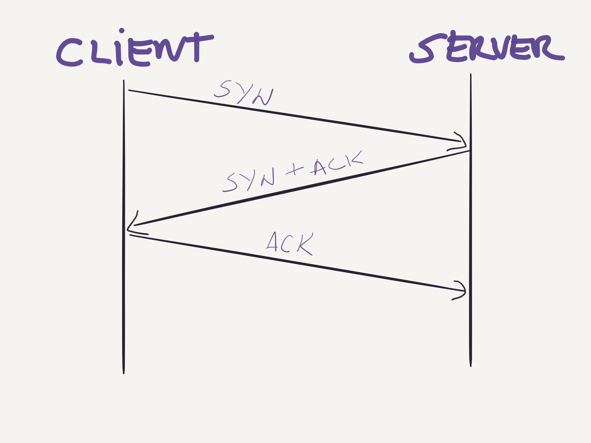
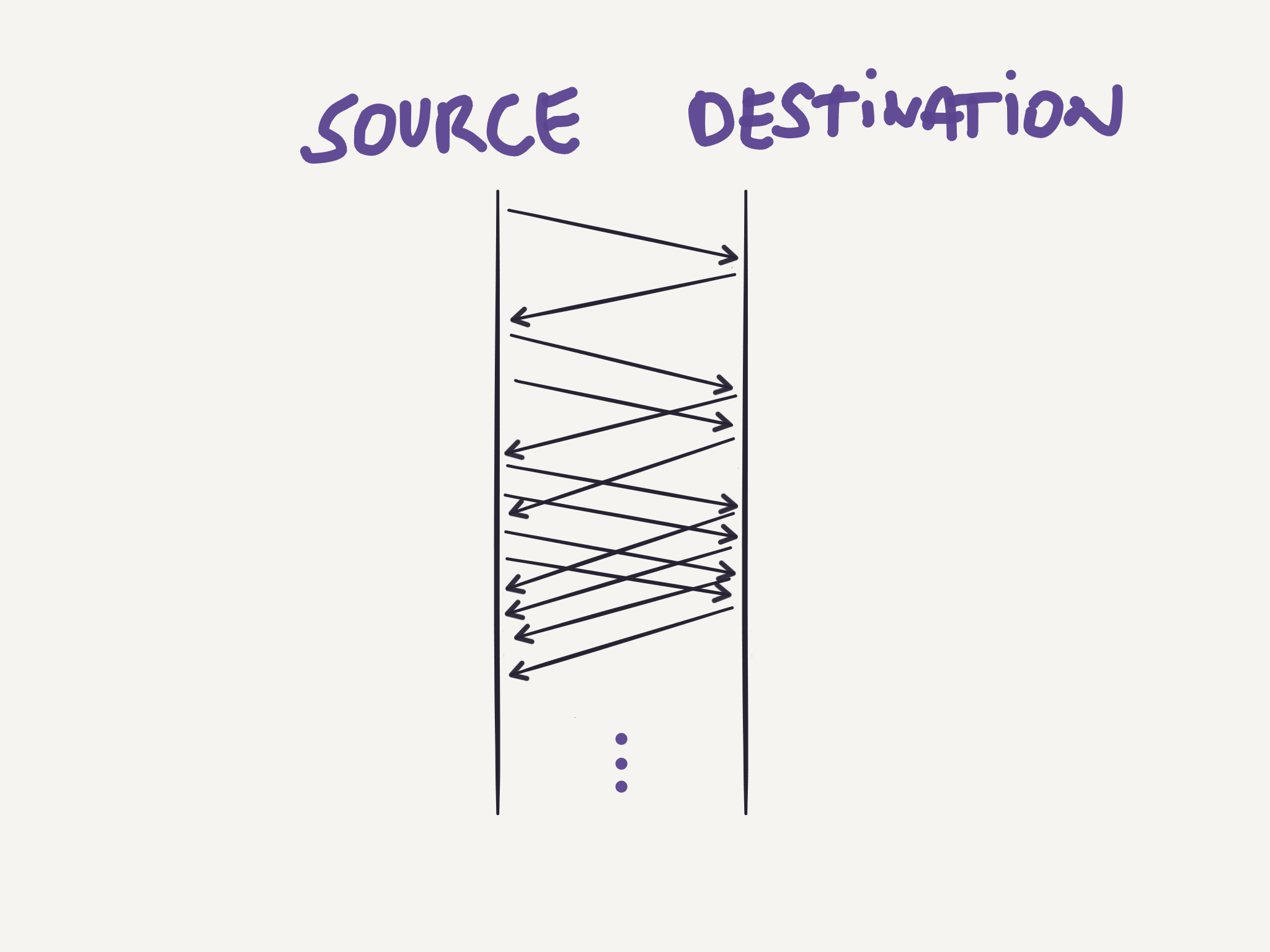
After setting up the connection, both ends can start sending data in form of segments as the image below shows:
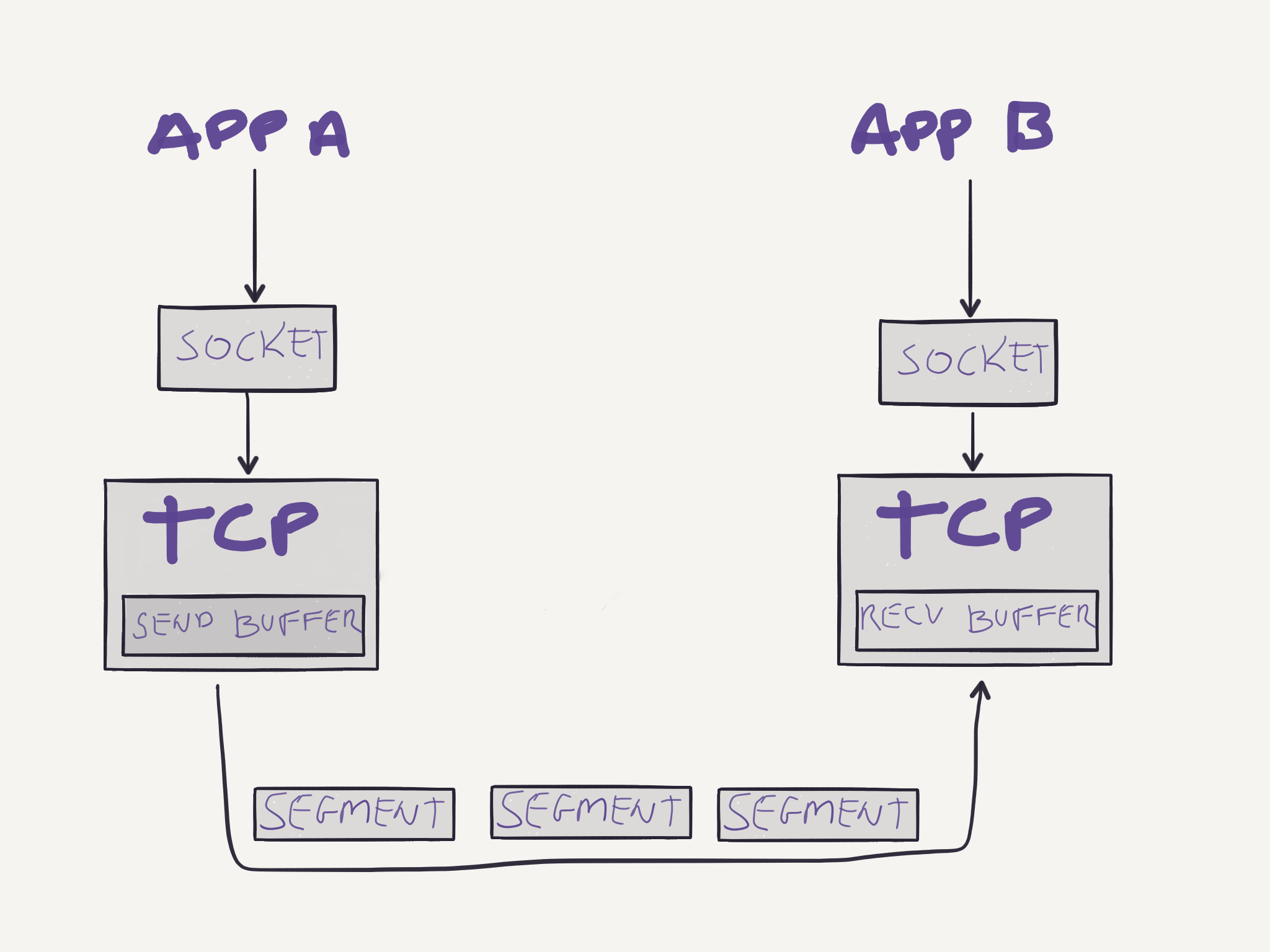
Note that since TCP is full-duplex, both parties will have a send and receive buffer, allowing data to flow in both directions.
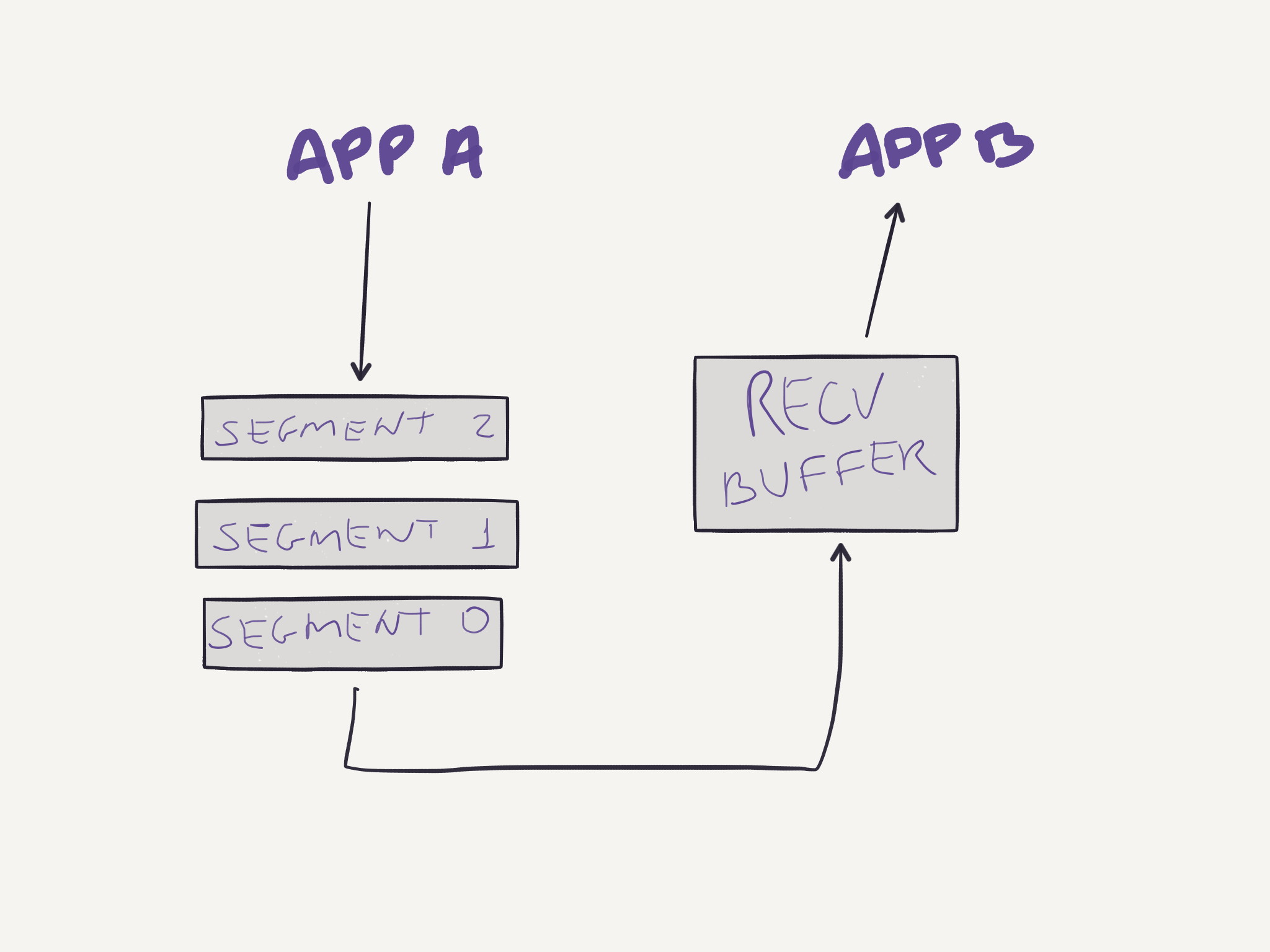
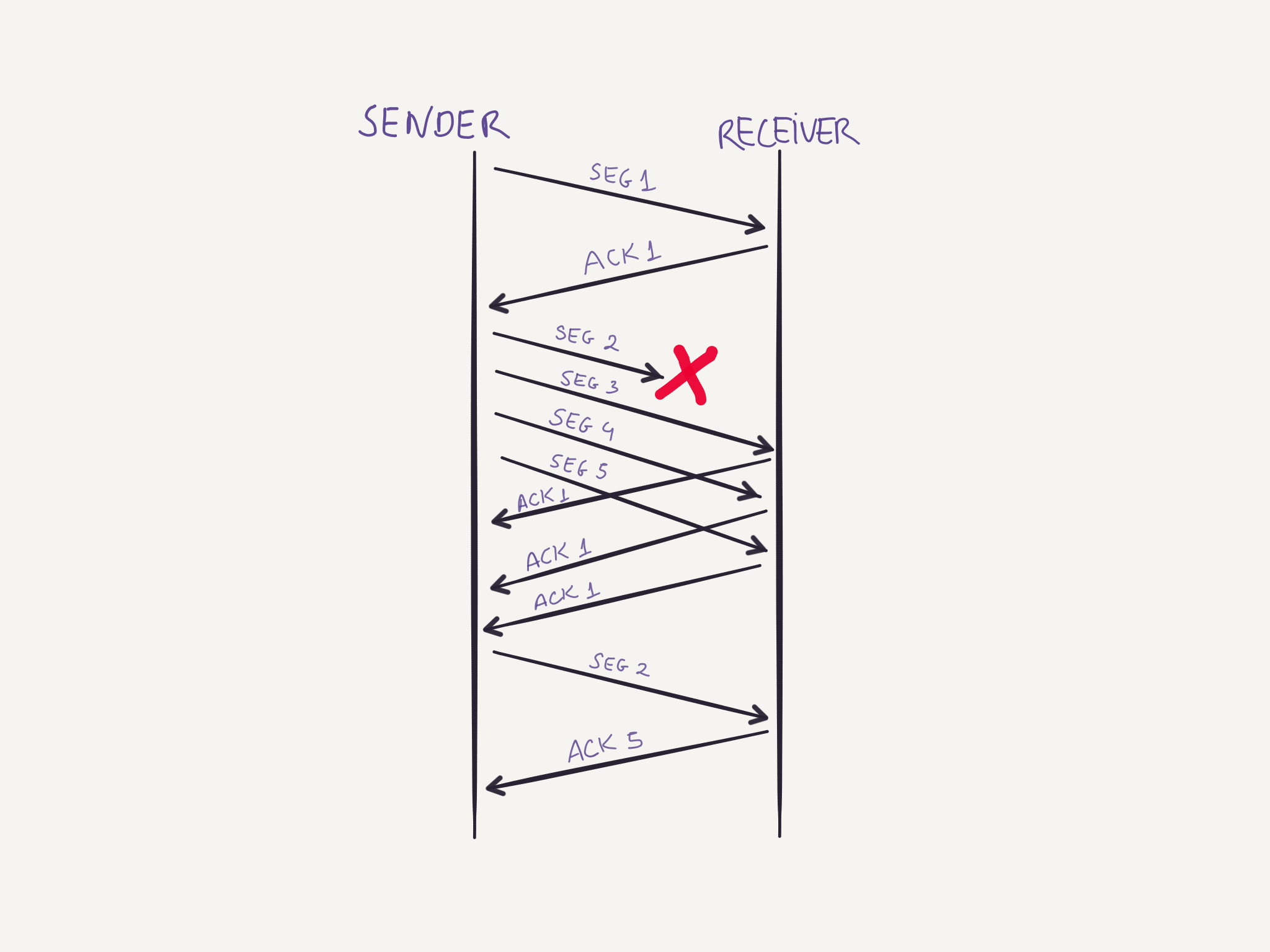
The IP network does not guarantee in-order delivery, does not guarantee datagram delivery, and does not guarantee the integrity of datagrams. TCP provides a reliable data transfer service on top of an unreliable IP network. The reliable service is possible via the usage of timers to retransmit packages that have not been acknowledged for a certain period of time. Sequencing numbers are used to guarantee in-order delivery of segments. Suppose an application sends three segments:
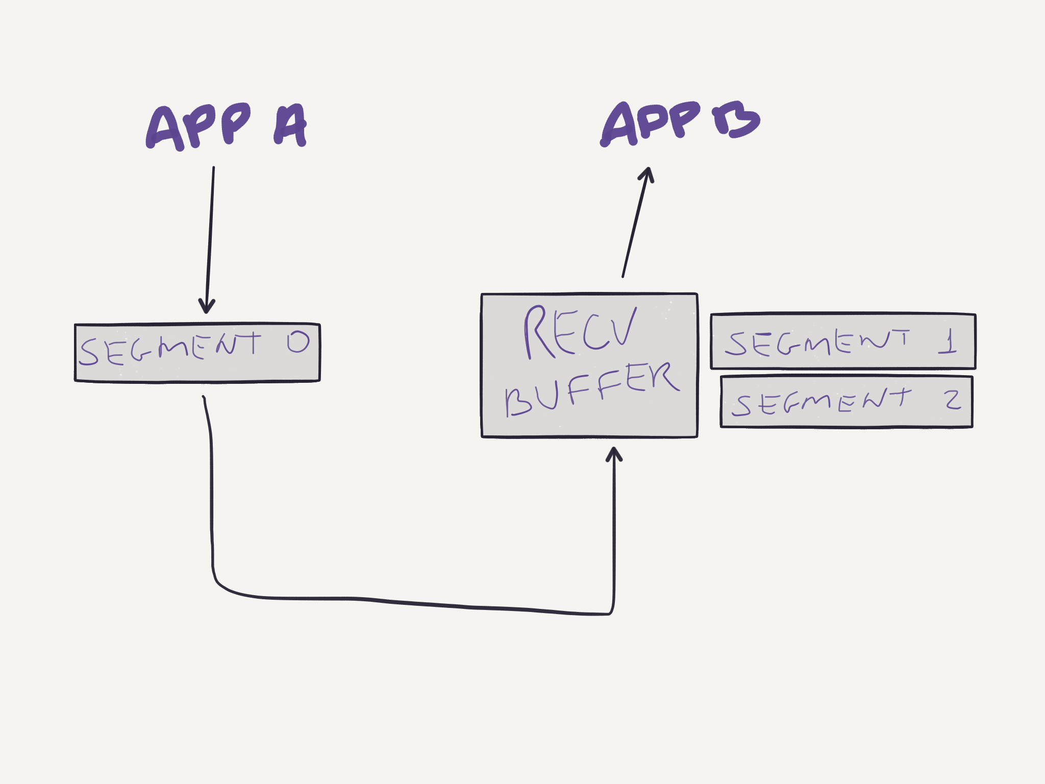
And the first segment is lost during the transmission:
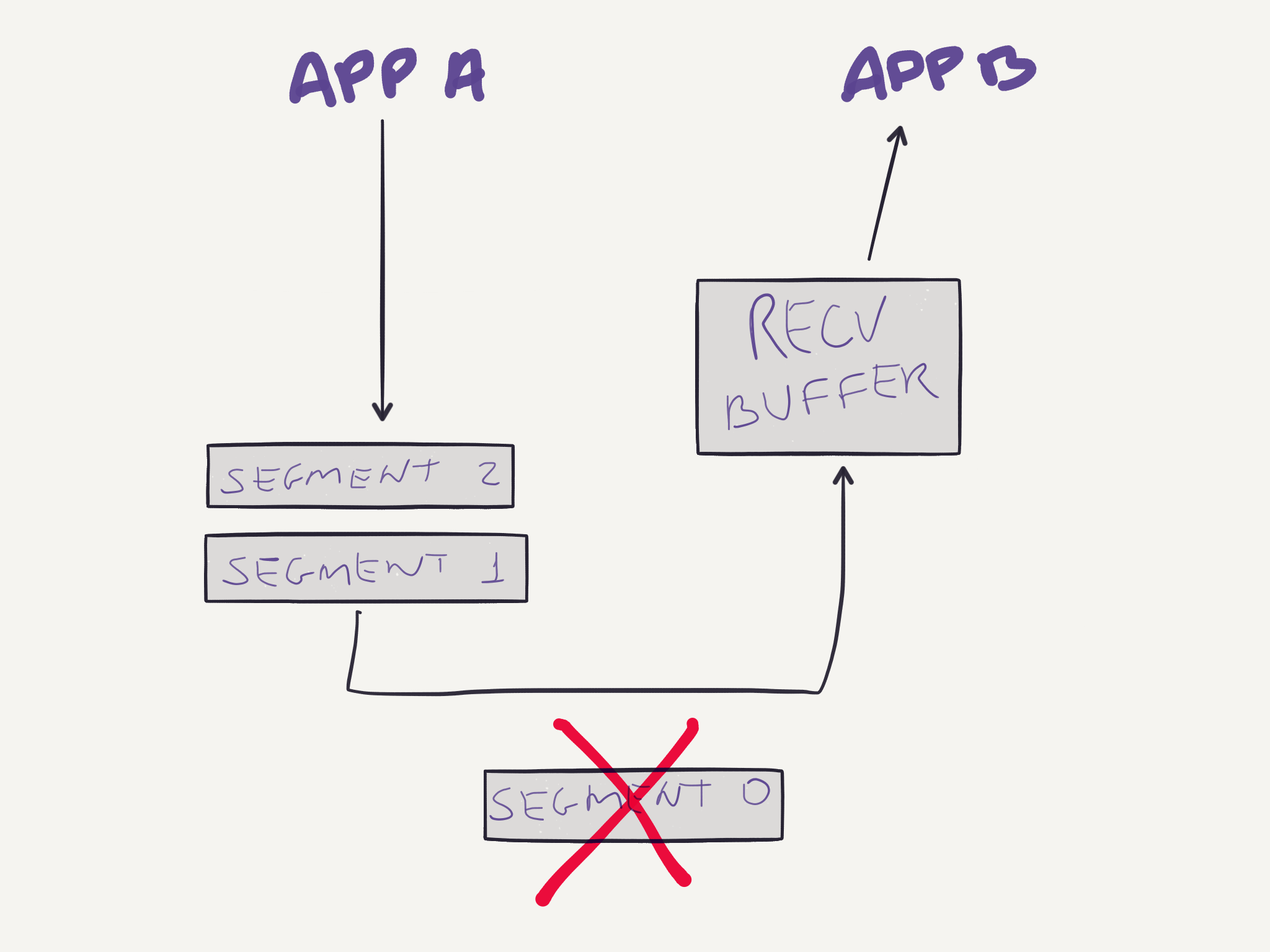
But the other two segments reach their destination. Then the receiving buffer will store these two segments while the first one is retransmitted:
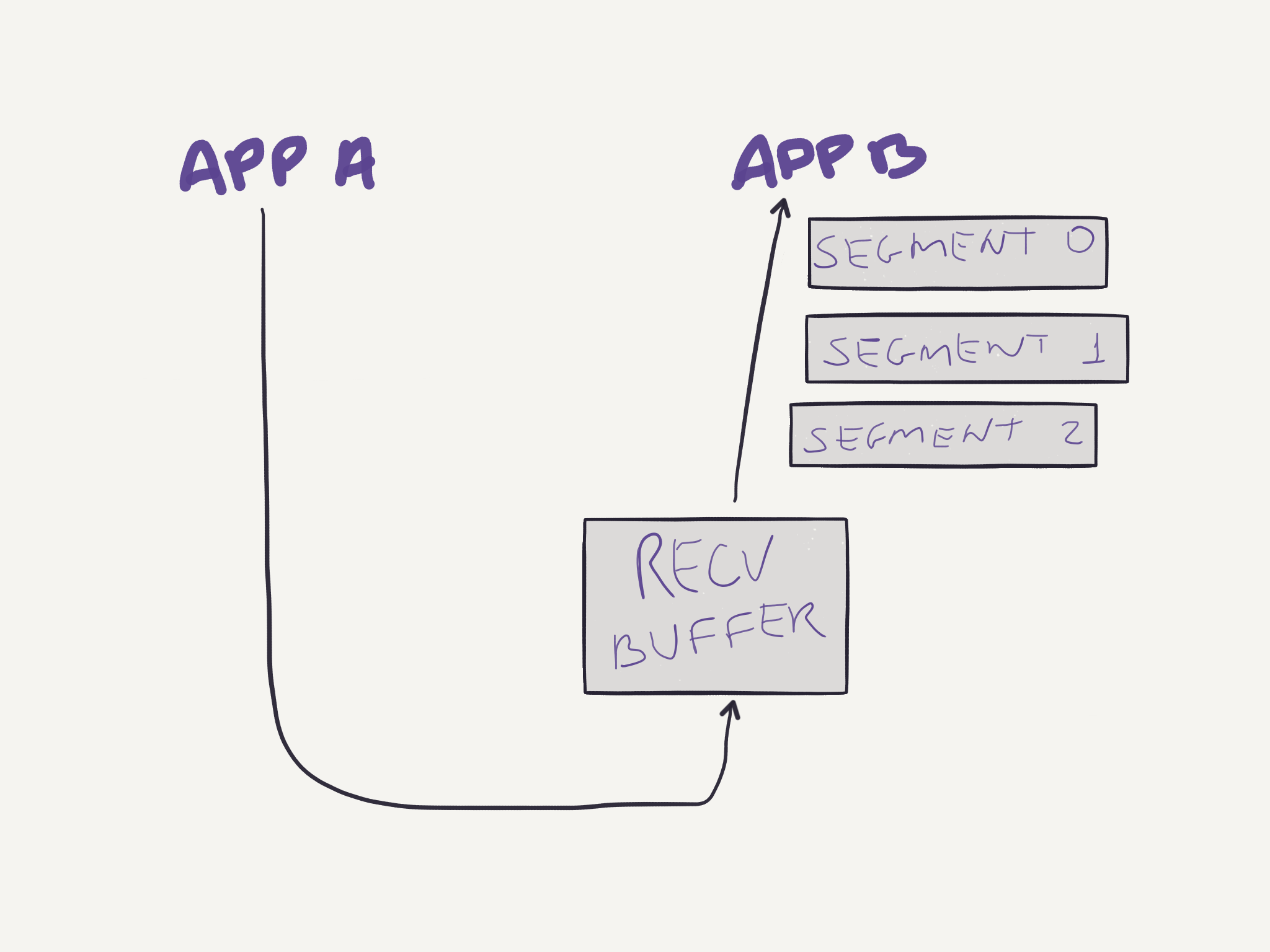
After all three segments are received, they are correctly reordered and delivered to the application:
The receive buffer shown above is not only used when out of order segments arrive. In fact, correct and in-order segments are placed in the receiving buffer and stay there until the application reads data from this buffer. If the application is busy and not reading data from the buffer, and the sending buffer keeps sending data, it might overflow the receive buffer. To prevent that from happening, TCP provides a flow-control service. Each party informs the other how much free space it has on its receive buffer in the Window Size field in the segment. The parties maintain two variables to compute this value:
LastByteRead: last byte read from the bufferLastByteRcvd: last byte received in the data stream and stored in the buffer
With those variables each party knows how much space it has available on its receive buffer:
WindowSize = RcvBuffer - (LastByteRcvd - LastByteRead)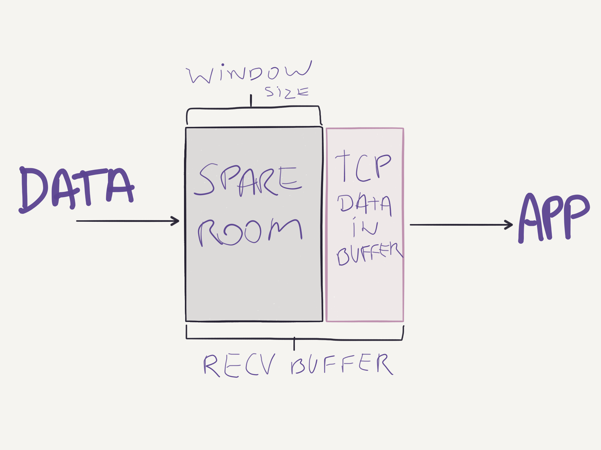
The sending party in question will also maintain variables to determine how much data it can send:
LastByteSent: last byte that was sentLastByteAcked: last byte that was acked by the receiver
Throughout the connection’s life, the sender will guarantee that:
LastByteSent - LastByteAcked <= WindowSizeIn the case the receive buffer of one party is full and the WindowSize is zero, the sender can’t simply stop sending segments because when the receiver frees space in its buffer it has no way of telling the sender that it can get back sending more data. So in this case when the WindowSize is zero, the sender continues sending a segment of 1 byte of data so that it will eventually be acknowledged with a new WindowSize value different than zero once the receiver process more data that was stored in the buffer.
To prevent a fast sender from overwhelming a network, TCP uses different congestion-control algorithms. It starts with a slow start, then switches to congestion avoidance and whenever congestion is detected (via a dropped packet), it switches to fast recovery mode. To do this, the TCP module at the sender keeps track of a variable called CongestionWindow, which has the value of how much traffic the sender can send. Remember that before it was said that the sender would always try to maintain the following constraint of data sent to the receiver:
LastByteSent - LastByteAcked <= WindowSizeThat’s not entirely true, though. Because TCP has the congestion-control mechanism, the sender actually maintains a different constraint:
LastByteSent - LastByteAcked <= min(CongestionWindow, WindowSize)The value of CongestionWindow is dynamic and changed differently depending on which congestion control algorithm is being used at the time. The different algorithms are:
Slow Start
This is the state any new TCP connection starts at. The CongestionWindow is set to 1 x MSS (Maximum Segment Size), and each time an ACK is received, the sender increases CongestionWindow by 1 x MSS. This way, at the beginning the sender will send one segment, when the ACK for that segment arrives, CongestionWindow will be changed to 2 x MSS, and the sender will send two segments, when the ACKs for those segments arrive, CongestionWindow will be 4 x MSS, the sender will then send four segments, and so on. This means that in slow start the rate at which segments are sent grows exponentially.
Congestion Avoidance
The process of doubling the number of segments to send clearly can’t continue forever, otherwise the network would be congested anyway at some point. A different algorithm is then used to change the rate of sending segments. In the congestion avoidance state, the rate grows linearly instead of exponentially as it happens in slow start mode.
In congestion avoidance mode, the sender increases its CongestionWindow to a fraction of MSS:
CongestionWindow = CongestionWindow + MSS * (MSS / CongestionWindow)But when does this algorithm starts being used? For that, there is another variable that the sender keeps track of. It’s ssthresh (slow start threshold). It’s initial value is set arbitrarily high and it’s reduced when congestion is detected. In case a timeout happens, the sender will assume the network is congested, then set ssthresh = CongestionWindow / 2, then set CongestionWindow = 1, and start the slow start process again. Eventually the CongestionWindow value will be higher than ssthresh and to avoid congesting the network again, when CongestionWindow >= ssthresh, the sender enters the congestion avoidance state and the rate starts growing linearly.
Fast Recovery
Fast recovery is a different algorithm also used for TCP congestion-control. Instead of waiting for a timeout to happen when a given segment is lost, the sender can detect early that something is not right when it receives duplicate ACKs. Then it can send the missing segment “early” in an attempt to avoid a timeout and getting back to the slow start state.
The receiver sends an ACK for each segment it receives. If it receives an out of order segment it will send an ACK for the last in order segment that was received. If the sender receives multiple ACKs for the same segment, it is reasonable to suspect that the segment was lost. For example, imagine the sender sends four segments, and the first is lost, the receiver will send ACKs for the previously acknowledged segment while keeping the newer segments in buffer until it receives the missing segment and reorder all of them.
After receiving 3 duplicate ACKs, the sender suspects the network might be congested and instead of waiting for the timeout to only then back down at the rate at it is sending segments, the sender enters the fast recovery mode. In this state the sender retransmits the missing segment, changes the value of ssthresh = CongestionWindow / 2, and also CongestionWindow = ssthresh + 3 * MSS. Each time a duplicate ACK is received, the sender can send a new segment since the acknowledgment means some segment has been received by the receiver, and thus, has left the network. The CongestionWindow is updated accordingly to accommodate the space for another segment, CongestionWindow = CongestionWindow + MSS. When a new ACK is received, the sender knows that the receiver received everything at this point, and the sender then switches to the congestion avoidance state described above.
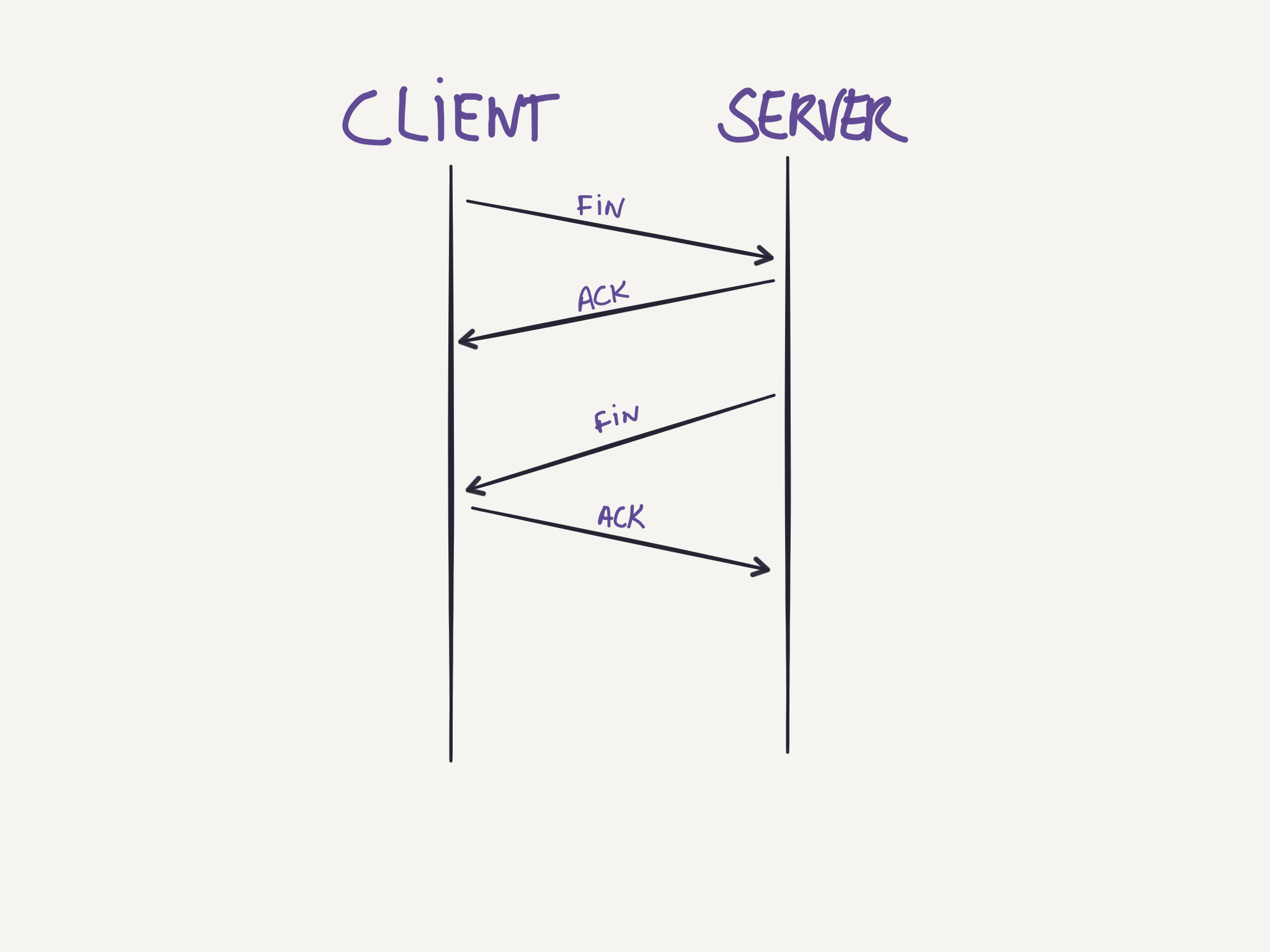
Connection teardown
Either side can start the process of terminating the connection. A four-way handshake is used for the process. The side wanting to terminate the connection sends a FIN segment, and enters a FIN_WAIT_1 state waiting for an ACK from the other side. After receiving this ACK it enters the FIN_WAIT_2 state and waits for a FIN segment from the other side, when that segment arrives, it sends an ACK and waits for a while in case the ACK needs to be retransmitted. After this time, the connection is formally closed and the resources are released.
Application layer
The protocols in the application layer provide some specific service between application process in different machines and specify how these processes communicate between them. These protocols define aspects such as:
- The types of messages exchanged;
- The syntax of the several message types;
- The semantics of the fields in such messages;
- Rules for determining when and how each process send and responds to messages.
Some well known application-layer protocols are: HTTP, DNS, NTP, DHCP, Telnet, TLS/SSL, etc.
Protocols
DNS
See DNS.
HTTP
See HTTP.
TLS/SSL
Transport Layer Security (TLS) and its predecessor, Secure Sockets Layer (SSL), are cryptographic protocols that provide a secure communication over a computer network. Connections running over TLS will have one or more of the following properties:
- Privacy: The connection will be private so that only the parties involved will be able to know what is being communicated between them. This is done by encrypting the data that is being transmitted.
- Authentication: The identity of the parties involved can be verified, preventing others to pretend they are someone else.
- Integrity: There are mechanisms allowing the parties to verify the integrity of the messages, to make sure the data was not corrupted.
Another interesting characteristic that may be provided depending on the configuration used for TLS, is a property called forward secrecy which means that if the encryption keys are disclosed in the future, it will not be possible to decrypt TLS communications that happened in the past.
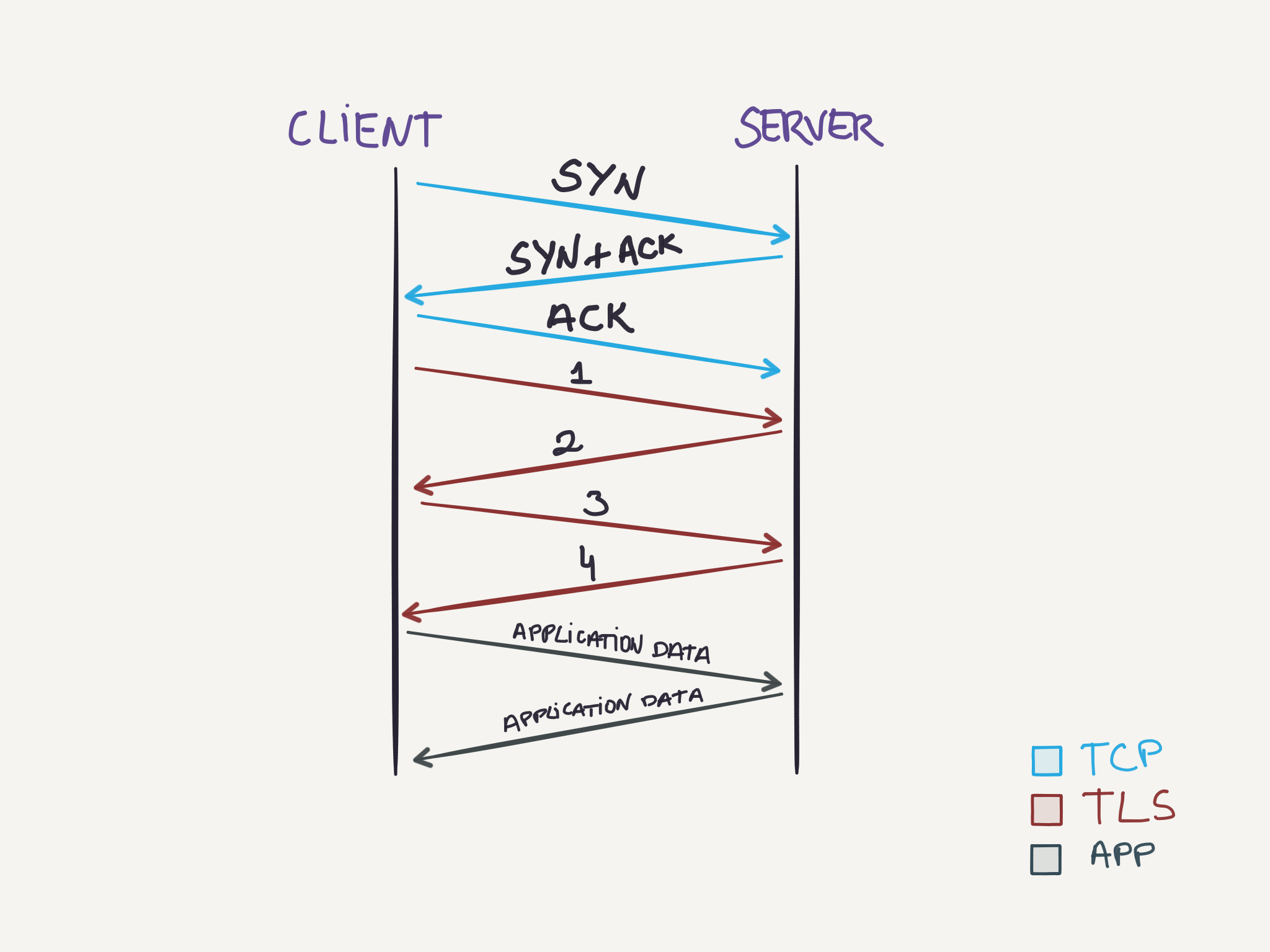
To setup the TLS connection the parties exchange messages, using a handshake procedure, to agree on some aspects of the connection:
- The TCP handshake to setup a TCP connection is done.
- The client sends the request for a TLS connection with a list of cipher suites it supports. (1)
- The server chooses one of the options from the cipher suites, that the server also supports and informs the client of its decision. (2)
- The prove to the client, that the server is in fact who it claims to be, the server also sends some form of identification, usually a certificate issued by a third party that the client also knows and trusts.
- The client confirms the validity of the certificate, and if it is valid, it can trust the server.
- Both parties exchange some common key to be used as the encryption key (3, 4). This could be either by using: * The server public-key (already sent) by the client to encrypt a random number that will be decrypted by the server with its private-key and then both parties will be able to generate the same session key to encrypt messages. * Or using Diffie-Hellman key exchange to generate a random and unique session key for encryption and decryption of messages. Connections using Diffie-Hellman have the forward secrecy property mentioned before.
Once the steps above complete successfully, both parties can securely start sending data between them using the session key generated in the process.
This text will not go over details about optimizations that are available for TLS. Beware that the client could start sending the TLS request together with the ACK from the TCP connection, and the TLS handshake can be abbreviated as well in case both parties have previously met.
For applications using TLS the process above is completely transparent to them. Usually, they will only deal with unencrypted data, as the task of encrypting/decrypting the data, and also setting up the TLS connection, is handled by the TLS layer.
An interesting TLS extension is SNI (Server Name Indication). This extension is used when a single machine hosts different applications and each application has its own TLS certificate. To be able to correctly setup and use the correct certificate, the client can indicate which hostname it is willing to talk to and then the server will see this value and choose the appropriate certificate to proceed with the TLS handshake.
TODO: DHCP, NTP, SSH, Telnet.
References
-

-

-

- blog.carlosgaldino.com
- Copyright © 2022 Carlos Galdino. All rights reserved.